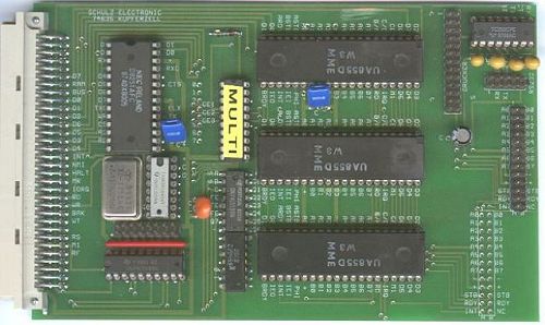
ZX96 Multi-I/O-Board
![]()
All I/O addresses can be selected as desired, but for the ZX96 we have some default settings used in our programs. So it is recommended leaving these settings as default. The addresses can be set with jumpers in this order:
| Pin | data port A | data port B | control A | control B | default |
| 0 | $07 | $0F | $17 | $1F | |
| 1 | $27 | $2F | $37 | $3F | |
| 2 | $47 | $4F | $57 | $5F | PIO 2 |
| 3 | $67 | $6F | $77 | $7F | |
| 4 | $87 | $8F | $97 | $9F | PIO 1 (printer) |
| 5 | $A7 | $AF | $B7 | $BF | (harddisc) |
| 6 | $C7 | $CF | $D7 | $DF | PIO 3 |
| 7 | $E7 | $EF | $F7 | $FF | $FF used by system! |
The USART is set default to $E3 und $EB.
The printer port uses PIO 1 with port A for data and port B for some controls and handshake. The remaining lines are used to set the programmable timer (HC294). Thus the baudrate for the USART can be set at 75, 150, 300, 600, 1200, 2400, 4800, 9600 Baud and above. All printer signals must directly (1:1) be connected to a Sub-D connector , only Pin 6 at the PCB must not be connected. Note that the output connectors for PIO 2 and 3 on the PCB have a different pinout to PIO 1, see print mask at the PCB. The RS232 output is similar to the printer, simply wire it 1:1 to a male Sub-D connector. Those generic COM brackets as used in PCs must not be used, they have a different wiring! In the schematic are already resistors shown connecting the /STB input of the PIOs to ground, but they must be soldered in at the solder side (no pins nor print mask at the PCB). To generate the /BUSCS for the driver board a GAL is used to combine all signals.
| schematic | 141 kB |
| schematic in EAGLE format | 91 kB |
| view at the PCB | 38 kB |