All the ZX-Keyboard expansions available have at least
two disadvantages: the connection with a flatcable (of limited possible
length) and the trouble of having to type in long sequences of frequently
used commands like, for example, when you quickly want to display the value
of RAMTOP. It would be nice to have an interface: connect it to the back
of a ZX, buy an AT keyboard and you're done. Shortly before finishing this
AT keyboard project, Peter Liebert-Adelt pointed out to me that in the
mean time the ZX fans in the USA weren't sleeping either.
Over there,
they built almost the same thing using TTL ICs. The circuit used is very
interesting, however it needs a XT Keyboard, which is not easy to get these
days. Also, I recently discovered Wilf Rigter's solution using a PIC processor.
The ZX81 AT-Keyboard Interface works with a normal PC-AT keyboard. When
I examined two different AT keyboards I noticed that one of these contained
a 80C49 and a few small ICs, while the other one had a custom IC and almost
no other parts. However, the connection to the keyboard is always the same:
a 4-wire cable that is used for supplying power and connecting a clock
and data line.
When a key is pressed, the clock and data lines change
from high signals to a pulse sequence which is always 12 bits long. In
this the main difference lies with a XT keyboard: it uses 8 bits instead.
The more detailed theory of data transfer involved has never really interested
me, it's not important that it should be 11 bits and one stopbit. The serial
data is now read with a microcontroller and decoded. Every normal key is
encoded in a 12 bit code, while some special keys result in multiple codes
of 12 bits each. When a key is released the keyboard always sends two codes:
one code for "key released" and a second code corresponding with the key
that was released, with a 2ms pause between these two codes. For example,
for the shift key it must be carefully evaluated: while shift is pressed
down and several keys are pressed after each other while holding shift
down, the keyboard starts with sending only one "shift" code and this must
be remembered until the code "Shift key released" is sent.
The interface in turn receives the serial data from the
keyboard, translates it into a 7 bit code and a single bit for "shift"
(more than 64 keys aren't really needed in our case) and relays the key
to the ZX81 by means of an EPROM (IC3), which contains the ZX-matrix.
This matrix-EPROM is quite a complicated matter, when
keeping in mind the ZX81 matrix key scanning procedure. (eg. described
in the the book "kleinen Hardwarebuch" by A. Deckers) For scanning the
ZX-keyboard, one of the 8 address lines A8-A15 is pulled low and the I/O
port $FE is read, where only D0 ... D4 are evaluated. That makes it possible
to locate each of the 40 seperate ZX81 keys. These 8 seperate address lines,
of which only one is active at a time, can be encoded into 3 lines. In
this process, the LS240 IC has two tasks: to buffer signals in order to
reduce bus load on the Z80 and to invert the logic signals. Without the
LS240, germanium diodes would be needed and the load on the address lines
would also be relatively high. A LS148 would have been ideal(would save
the diodes and an LS240), but I didn't have one of those available at the
time. So finally we have 3+8 inputs which result in 5 outputs that need
to be encoded in a specific manner.
With this Matrix-EPROM any key
of the AT keyboard can be transformed. For example, the code for the "Del"
key can be relayed to the ZX81 as "Shift+0". The same applies to the keys
,;.:+-*/ etc. This way, these keys can be used directly, without needing
to press "shift". Every AT keyboards has an extra numerical key block -
these keys can also be transformed resulting in much easier input of numbers.
For the translation of the 12 bit AT keyboard codes into the 7 eprom
bits, a second code table is used
in the program of the microcontroller. This allows us to make smart use
of a feature of the 8048: banking. Using the keys F11 and F12, these banks
can be switched and the keyboard layout can be completely altered. The
program is the same for all banks, only the code table area is different.
Most frequently, an alternative cursor key layout is needed because many
ZX81 programs evaluate the 5, 6, 7, 8 cursor keys differently. Some require
shift to be pressed first and some work without shift.
Because in our case there is an 'intelligent being' between the AT keyboard
and the ZX, we can even attribute entire key sequences to a single AT key:
the microcontroller can simply process a "keyboard macro". That's why I
have attributed the annoying keyboard commands that I most frequently need
to the function keys, which includes the nerve-killing PRINT PEEK 16389+
... This matter is solved with a relatively simple straight-forward software
solution, but it works. Programming fans can also consider for themselves
if it would be possible to store such a keyboard macro in the microcontroller's
RAM which could result in user-programmable function keys. It's also possible
to use a 2732 as the matrix EPROM. In that case, a switch would allow to
choose from two different keyboard layouts, (eg. Spectrum or Power3000)
in case the F11 and F12 options are already used.
Finally a few things needed for building this project:
(explanations in certain documents are in German)
So how does the entire circuit work? Let's assume that
the "Q" key is pressed. This means that the microcontroller outputs "10".
In the ZX81 keyboard matrix the "Q" connects A10 with D0. The ZX81 knows
that when it reads D0=low while A10=low, the "Q" key is pressed. So the
output to the ZX81 must be $FE. (D0=low) The matrix-EPROM can be viewed
as devided into 8 blocks of 256 bytes each. One block represents a matrix
address line of the ZX81. When A10=low, the 3rd block -counted from A8-
is valid. So the EPROM inputs are: A0...A7="10", A8=A9=high, A10=low. At
this address (778) the matrix EPROM should contain the value $FE.When shift
is pressed, bit 7 of the microcontroller (A7 of the matrix EPROM) will
be high which results in a +128 shift of the matrix EPROM addresses. In
order to make the ZX81 also register the shift, the upper 128 bytes of
the A8 EPROM block must always have bit0=low. (address 128 through 255)
A key that is scanned with A8 but also has shift pressed is encoded by
setting two bits low.
Documented
Listing (scans)
245 kB
Binary file
of the program-EPROM IC2
2 kB
Binary file
of the matrix-EPROM IC3
2 kB
Sourcecode
13 kB
Circuit Diagram
52 kB
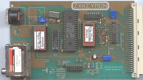
Picture of the finished board
31 kB
07/01 Kai Fischer